What Does It Mean When an Electrical or Optical Channel is PAM-4 or NRZ?
PAM-4 and NRZ are two different modulation techniques that are used to transmit data over an electrical or optical channel. Modulation is the process of changing the characteristics of a signal (such as voltage, amplitude, or frequency) to encode information. PAM-4 and NRZ have different advantages and disadvantages depending on the channel characteristics and the data rate.
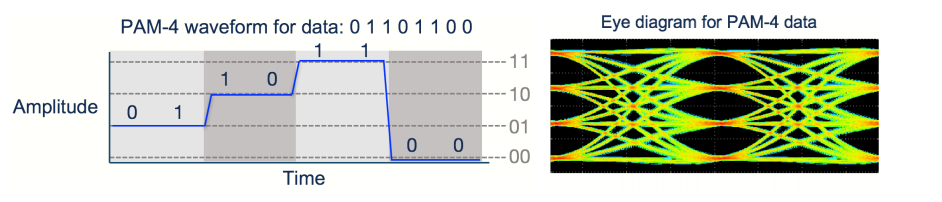
PAM-4 stands for Pulse Amplitude Modulation 4-level. It means that the signal can have four different levels of amplitude (or voltage), each representing two bits of information. For example, a PAM-4 signal can use 0V, 1V, 2V, and 3V to encode 00, 01, 11, and 10 respectively. PAM-4 can transmit twice as much data as NRZ for the same symbol rate (or baud rate), which is the number of times the signal changes per second. However, PAM-4 also has some drawbacks, such as higher power consumption, lower signal-to-noise ratio (SNR), and higher bit error rate (BER). PAM-4 requires more sophisticated signal processing and error correction techniques to overcome these challenges. PAM-4 is used for high-speed data transmission such as 400G Ethernet.
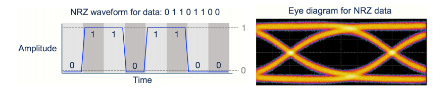
NRZ stands for Non-Return-to-Zero. It means that the signal can have two different levels of amplitude (or voltage), each representing one bit of information. For example, a NRZ signal can use -1V and +1V to encode 0 and 1 respectively. NRZ does not return to zero voltage between symbols, hence the name. NRZ has some advantages over PAM-4, such as lower power consumption, higher SNR, and lower BER. NRZ is simpler and more robust than PAM-4, but it also has a lower data rate for the same symbol rate. NRZ is used for short-distance data transmission such as 100G Ethernet.
When a signal is referred to as 鈥?5Gb/s NRZ鈥澛爋r 鈥?5G NRZ鈥? it means the signal is carrying data at 25 Gbit / second with NRZ modulation. When a signal is referred to as 鈥?0G PAM-4鈥? or 鈥?00G PAM-4鈥澛爄t means the signal is carrying data at a rate of 50 Gbit / second, or 100 Gbit / second, respectively, using PAM-4 modulation.
FAQS
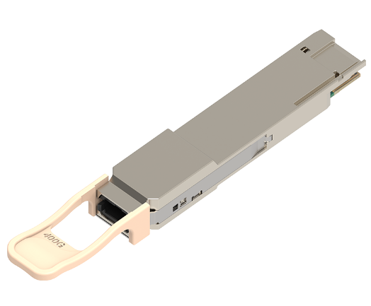
Q: 400G QSFP-DD vs 400G OSFP/CFP8: What are the differences?
A: The table below includes detailed comparisons for the three main form factors of 400G transceivers.
| 400G Transceiver | 400G QSFP-DD | 400G OSFP | CFP8 |
|---|---|---|---|
| Application Scenario | Data center | Data center & telecom | Telecom |
| Size | 18.35mm× 89.4mm× 8.5mm | 22.58mm× 107.8mm× 13mm | 40mm× 102mm× 9.5mm |
| Max Power Consumption | 12W | 15W | 24W |
| Backward Compatibility with QSFP28 | Yes | Through adapter | No |
| Electrical signaling (Gbps) | 8× 50G | ||
| Switch Port Density (1RU) | 36 | 36 | 16 |
| Media Type | MMF & SMF | ||
| Hot Pluggable | Yes | ||
| Thermal Management | Indirect | Direct | Indirect |
| Support 800G | No | Yes | No |
Q: How does the QSFP+ to SFP+ fiber convertor allow 4x 10G?
A: To enable 4x 10G connectivity, a QSFP+ to SFP+ fiber converter utilizes a breakout cable. This cable splits the 40G channel provided by the QSFP+ transceiver into four individual 10G channels, each connected to an SFP+ transceiver. Essentially, the converter breaks down the high-speed 40G signal into four separate 10G signals, allowing each SFP+ port to transmit data at 10G speeds. This configuration is beneficial for scenarios where equipment with SFP+ interfaces needs to communicate with a device equipped with a QSFP+ port, providing flexibility and compatibility in networking setups.
Q: What does “SR8”, “DR4”, “XDR4”, “FR4”, and “LR4” mean?
A: “SR” refers to short range, and “8” implies there are 8 optical channels. “DR” refers to 500m reach using single-mode fiber, and “4” implies there are 4 optical channels. “XDR4” is short for “eXtended reach DR4”. And “LR” refers to 10km reach using single-mode fiber.
Q: Can I plug an OSFP transceiver module into a QSFP-DD port?
A: No. QSFP-DD and OSFP are totally different form factors. For more information about QSFP-DD transceivers, you can refer to 400G QSFP-DD Transceiver Types Overview. You can use only one kind of form factor in the corresponding system. E.g., if you have an OSFP system, OSFP transceivers and cables must be used.
Q: What other breakout options are possible apart from using OSFP modules mentioned above?
A: OSFP 400G DACs & AOCs are possible for breakout 400G connections. See 400G Direct Attach Cables (DAC & AOC) Overview for more information about 400G DACs & AOCs.
Q1: What is the difference between QSFP28 ER4 and QSFP28 ER4 Lite Module?
A: The QSFP 100G ER4 has a series of BER requirements of better than 1E-12 without FEC optical modules. However, the receiving sensitivity of 100G QSFP28 ER4 is not satisfied with the existing APD technology. Therefore, many optical module manufacturers/suppliers defined a non-standard 100Gbase ER4 Lite module with a QSFP28 package where the largest transmission distance is up to 40km with FEC or 30km without FEC.?Walsun provides the QSFP28 100G ER4 Lite module compliant with the Ethernet 100Gbase ER4 Lite standard to meet the harshest external operating conditions including temperature, humidity, and EMI interference.
Q2: How does the QSFP 100G ER4 Module differ from the QSFP28 4WDM?
A: The QSFP 100G ER4 optical transceiver supports dual 100G Ethernet applications while the 100G QSFP28 4DWM only supports 100G Ethernet applications. The commons and differences are listed below.
| Form Type | QSFP28 ER4 | QSFP28 4WDM | ||
|---|---|---|---|---|
| Max Data Rate | 25.78125Gbps/27.95Gbps | 25.78125Gbps | ||
| Max Cable Distance | 40km | 10km | 20km | 40km |
| Center Wavelength | 1295.56nm, 1300.05nm, 1304.58nm, 1309.14nm | 1271nm, 1291nm, 1311nm, 1331nm | 1295.56nm, 1300.05nm, 1304.58nm, 1309.14nm | 1295.56nm, 1300.05nm, 1304.58nm, 1309.14nm |
| FEC Requirement | Without FEC (BER 1E-12) | With FEC (BER 5E-5) | ||
| Receiver | SOA+PIN ROSA | PIN ROSA | PIN ROSA | APD ROSA |
| Cooling Requirement | Cooled | Uncooled | Cooled | Cooled |