In fiber optics, advancements continue revolutionizing how we transmit and receive data. One such breakthrough is the development of Polarization Maintaining Fiber (PMF). This specialized type of fiber has gained significant attention and popularity due to its ability to preserve the polarization state of light signals. This blog post will introduce the working principle of PM fiber, fast and slow axis, beat length, and extinction ratio.
What is Polarization?
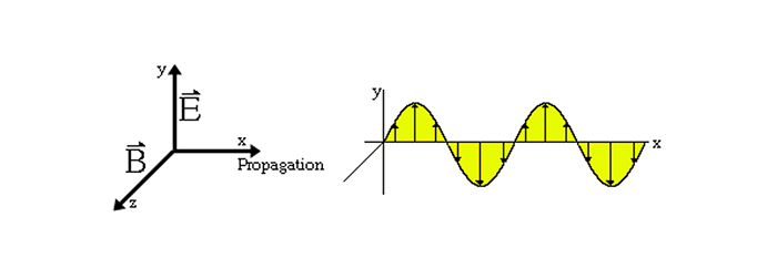
The direction and amplitude of the vibrating electric field trace the path in time as light travels through a point in space, and the polarized light wave signal is represented by electric and magnetic field vectors at right angles to each other in the transverse plane (the plane perpendicular to the direction of travel). It consists of an oscillating electric field denoted E, and a magnetic field denoted B. Its properties can be described by studying its electric field E, although we can also describe light and its effects in terms of magnetic fields.
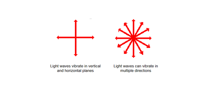
Light waves can vibrate in many directions. Those that vibrate in one direction — in a single plane, such as up and down — are called polarized light. A Light that vibrates in more than one direction — in more than one plane, such as up/down and left/right — is called unpolarized light.
What is Polarization Maintaining Fiber?
Theoretically speaking, a fiber with a circular core should not produce birefringence, and the polarization state of the fiber will not change during propagation. However, in practice, during the production process, conventional optical fibers will be subjected to external forces and other reasons, which will cause the optical fiber to be uneven in thickness or bent, which will cause birefringence. When the optical fiber is affected by any external interference, such as wavelength, bending degree, temperature, etc., the polarization state of light will become disordered when it is transmitted in a conventional optical fiber.
This problem of polarization state change can be solved by the application of polarization-maintaining fiber, but it does not eliminate the birefringence phenomenon in the fiber but eliminates the influence of stress on the polarization state of the incident light by designing the geometry of the fiber.
How does PM fiber affect birefringence in fiber? During the drawing process of PM fiber, when linearly polarized light is transmitted along one characteristic axis of the fiber, part of the optical signal will be coupled to another characteristic axis perpendicular to it. Eventually, the extinction performance will decrease the ratio of the outgoing polarized light signal, thereby affecting the birefringence effect.
Classification of Polarization Maintaining Fiber
Polarization-maintaining fibers generally include geometrical polarization-maintaining fibers and stress-type polarization-maintaining fibers. The structure of geometrical polarization-maintaining fibers is mainly elliptical core polarization-maintaining fibers, which are used in some special applications.
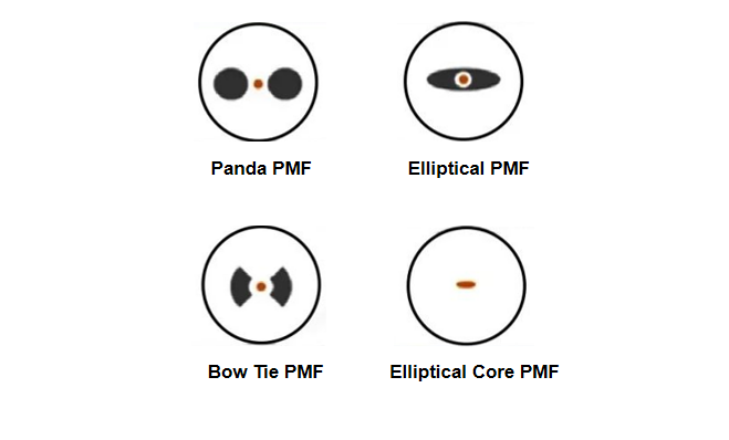
Stressed Polarization Maintaining Fibers mainly include panda, ellipse, bow tie, and ellipse core PMF. Their pros and cons are:
(1) Panda PMF: The size of the preform is large and suitable for mass production. But the area of the stress zone is large and sensitive to temperature.
(2) Elliptical PMF: Good stability. But the size of the preform is small, the stress is concentrated at the top of the stress zone, and the cutting is easy to crack.
(3) Bow Tie PMF: High birefringence. However, it is difficult to control the geometry of the fiber core and the size of the preform is small.
(4) Elliptical Core PMF: Insensitive to temperature, easy to grind the cross-section. But weak birefringence.
Panda polarization maintaining fiber has natural advantages in terms of fiber performance, whether it is birefringence, geometric characteristics, structural symmetry, or longitudinal uniformity of fiber. At the same time, since the manufacturing process of the panda-type polarization-maintaining fiber does not need to be completed in one step, the independent manufacturing of each component can effectively control the structure and composition of the fiber. It can ensure that each preform can draw tens of kilometers or even more than one hundred kilometers of uniform polarization-maintaining optical fiber products, which is suitable for mass production, so Panda polarization-maintaining fibers are commonly used.
What are the Parameters of Polarization Maintaining Fiber?
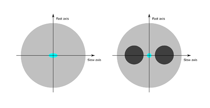
1.Fast Axis and Slow Axis
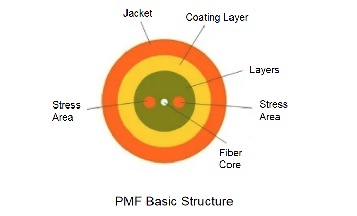
Two stress zones different from the expansion coefficient of the fiber cladding are made on both sides of the single-mode fiber core. During the drawing process of the fiber preform, the fiber is rapidly dropped from a high temperature to a lower temperature. During the cooling process, 2 Each stress zone contracts, the amount of which is hindered by the surrounding quartz. The core of the optical fiber is pulled outward along the direction of the line connecting the two stress zones (x-axis), and there is a compressive stress in the direction perpendicular to it (y-axis), thereby generating stress birefringence in the core and forming 2 axes that are orthogonal to each other.
The refractive index of the two main axis directions is different. In the direction of stress application, the effective refractive index of the fiber core is higher, and the transmission speed of light is slower, which becomes the slow axis, which is the main axis of the polarization-maintaining fiber. In the other direction, light travels faster, known as the fast axis.
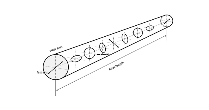
2.Beat Length
The beat length of the polarization-maintaining fiber is characterized by the length of the fiber transmitted by the complex polarization state of the transmitted light in the polarization-maintaining fiber jumper to complete a periodic change.
Physically, the beat length reflects the fiber length Lp corresponding to the phase difference between the two linearly polarized modes of the fundamental mode changing from 0 to 2Π.
The shorter the beat length, the more elastic the fiber is to the irregular effect of polarization, and the stronger the polarization-maintaining ability of the fiber is to linearly polarized light.
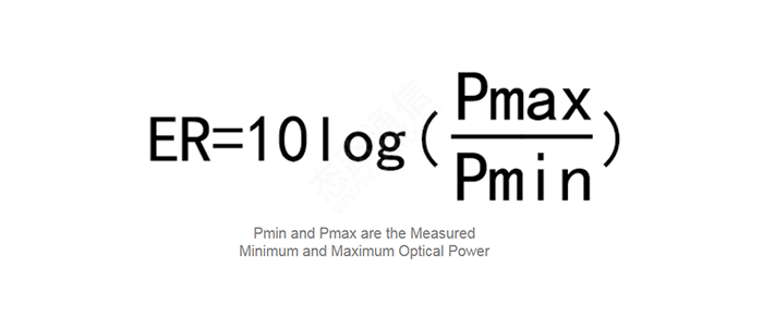
3.Extinction Ratio
Aligning the polarized light polarization direction with one of the axes, the polarization component divided into the other axis will be small, thereby maintaining the polarization state of the transmitted light. At this time, the extinction ratio (ER) parameter is introduced to reflect the degree to which the optical fiber maintains the polarization state.
When the polarization direction of polarized light is aligned with one of the fast and slow axes, two orthogonal polarization modes are generated by the components. The ratio of the polarization component along the original direction axis to the polarization component in the vertical direction is the extinction ratio. The extinction ratio is an important parameter to measure the quality of the polarizer, the larger the extinction ratio, the higher the quality of the polarizer.
Note: The beat length describes the state change of the light polarization transmission; the extinction ratio describes the polarization state of the light after transmission.
Working Principle of Polarization Maintaining Fiber
Coupling and alignment of polarization modes through precise connector keying. Compared with traditional optical fiber jumpers, it has the advantages of transmitting polarized light signals through polarization-maintaining fibers, ensuring that the direction of linear polarization remains unchanged, improving the coherent signal-to-noise ratio, and realizing high-precision measurement of physical quantities.
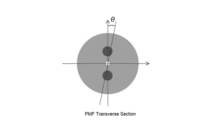
The polarization-maintaining connector is an important component for the coupling of two polarization-maintaining fibers. It ensures that the polarization mode of the two polarization-maintaining fibers during coupling maintains the original polarization state of the polarized light and maintains a high extinction ratio for transmission. This requires accurate docking of the slow axis or fast axis of the two optical fibers to minimize the θ angle error. Aligning the polarized light polarization direction with one of the axes, the polarization component divided into the other axis will be small, thereby maintaining the polarization state of the transmitted light. The polarization-maintaining angle and extinction ratio reflect the quality of maintaining the polarization state.
Requirements for Polarization Maintaining Fiber
The stress rod is parallel to the fiber core, and the applied stress produces birefringence in the fiber core, which is conducive to the polarization propagation of light in only one direction, so as to maintain the polarization maintaining work. Panda stress rods are cylindrical, while bowtie stress rods are trapezoidal prisms. Generally speaking, the quality of the polarization maintaining fiber depends on the incident state of the polarized light, and the polarization state of the polarized light is required to be aligned with the fast and slow axes of the polarization maintaining fiber.
(1) Termination: When a PM fiber is terminated with a fiber optic connector, it is very important that the stress rod is aligned with the connector, usually with the connector key.
(2) Splicing: Polarization maintaining fibers also need to be extra careful when splicing. When the fibers are fused together, not only must the X, Y, and Z alignment be perfect, but the rotational alignment must also be perfect so that the stress rods align accurately.
(3) Consistent: The launch condition of the fiber end face must be consistent with the direction of the transverse major axis of the fiber cross section.
Conclusion
PM Fiber emerged as a breakthrough technology in the field of optical fiber. Its ability to maintain the polarization state of optical signals over long distances addresses a key challenge faced by traditional fiber optic communication systems. With their outstanding properties and diverse applications, PMFs pave the way for enhanced data transmission, precise sensing, and advanced optical systems. As research and development continue, we can expect further developments in PMFs, leading to more complex and reliable optical solutions in the future.