There are a few different ways to do this (as discussed earlier in this document), summarized below.
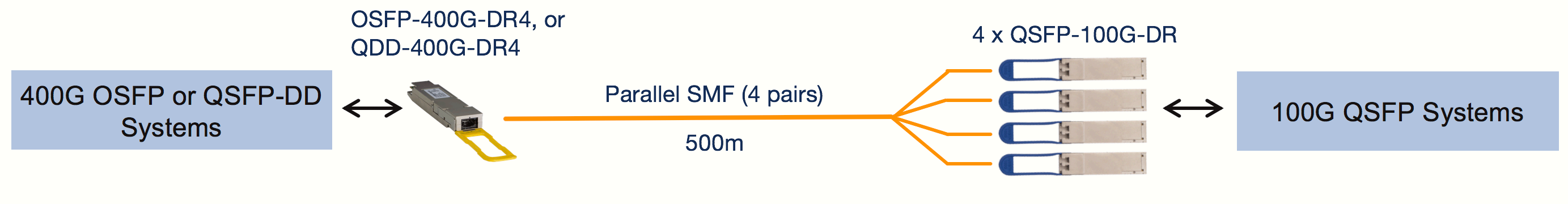
i) OSFP-400G-DR4 (or QDD-400G-DR4) to 4 x QSFP-100G-DR over 500m SMF
Connect up to 4 x QSFP-100G-DRs to a single OSFP-400G-DR4 (or QDD-400G-DR4). The QSFP-100G-DR can plug into any Arista 100G QSFP port.
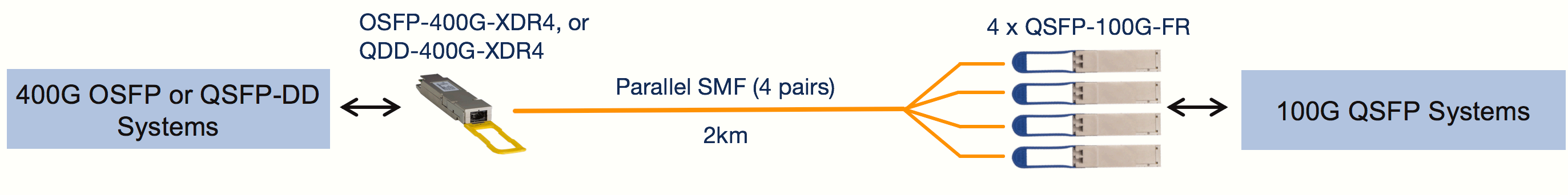
ii) OSFP-400G-XDR4 (or QDD-400G-XDR4) to 4 x QSFP-100G-FR over 2km SMF
Connect up to 4 x QSFP-100G-FRs to a single OSFP-400G-XDR4 (or QDD-400G-XDR4). The QSFP-100G-FR can plug into any Arista 100G QSFP port.
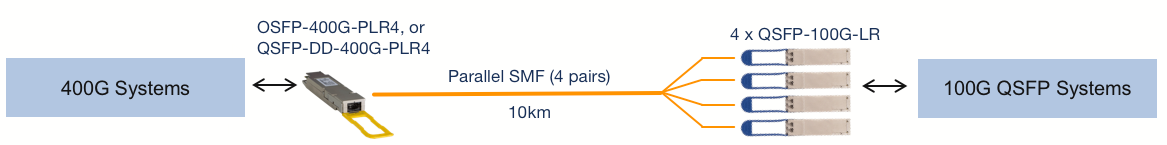
iii) OSFP-400G-PLR4 (or QDD-400G-PLR4) to 4 x QSFP-100G-LR over 10km SMF
Connect up to 4x QSFP-100G-LRs to a single OSFP-400G-PLR4 (or QDD-400G-PLR4). The QSFP-100G-LR can plug into any Arista 100G QSFP port.
iv) H-O400-4Q100-xM (or H-D400-4Q100) to 4x QSFP100 ports with Active Copper DACs, 1m-5m
Connect up to 4x 100G QSFP ports to a single 400G OSFP or QSFP-DD port. The QSFP end of the active breakout DAC includes a gearbox chip that converts 2x50G PAM-4 electrical signals into a 4x 25G NRZ interface, the modulation format used in legacy 100G QSFP ports.
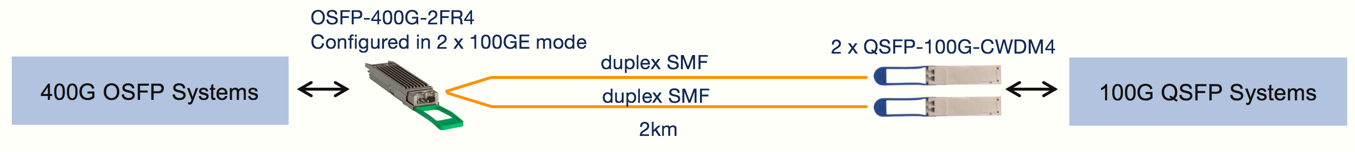
v) OSFP-400G-2FR4 to 2 x QSFP-100G-CWDM4 over 2km SMF
If an OSFP port is configured for 2 x 100G (i.e. 200G total bandwidth), the OSFP-400G-2FR4 module can be used to connect to 2 x QSFP-100G-CWDM4 transceivers over duplex single-mode fibers.
Configuring an OSFP port for 200G total bandwidth means each of the 8 electrical lanes to/from the OSFP operates at 25Gb/s NRZ, the same modulation format used in legacy 100G QSFP ports.
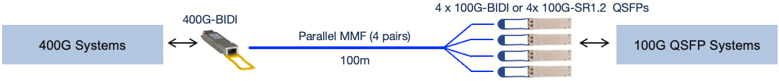
vi) OSFP-400G-SRBD (or QDD-400G-SRBD) to 4x QSFP-100G-SRBD or 4x 100G-SR1.2 QSFPs over 100m MMF
Connect up to 4x QSFP-100G-SRBD, or 4x 100G-SR1.2 QSFPs to a single 400G-BIDI module.
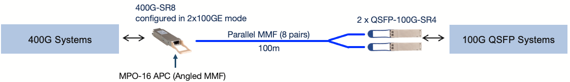
vii) OSFP-400G-SR8 (or QDD-400G-SR8) to 2 x QSFP-100G-SR4 QSFPs over 100m MMF
If an OSFP port is run at 200G total bandwidth, the OSFP-400G-SR8 module can be used to connect to 2 x QSFP-100G-SR4 transceivers using a multimode breakout cable.
viii) Passive DAC breakout cable using CAB-O-2Q-400G-xM / CAB-O-2Q-200G-xM or CAB-D-2Q-400G-xM / CAB-D-2Q-200G-xM
If the OSFP or QSFP-DD port is run at 200G total bandwidth, a passive DAC breakout cable can be used to connect an OSFP or QSFP-DD port into 2x 100G QSFP ports.

FAQS
Q: 400G QSFP-DD vs 400G OSFP/CFP8: What are the differences?
A: The table below includes detailed comparisons for the three main form factors of 400G transceivers.
| 400G Transceiver | 400G QSFP-DD | 400G OSFP | CFP8 |
|---|---|---|---|
| Application Scenario | Data center | Data center & telecom | Telecom |
| Size | 18.35mm× 89.4mm× 8.5mm | 22.58mm× 107.8mm× 13mm | 40mm× 102mm× 9.5mm |
| Max Power Consumption | 12W | 15W | 24W |
| Backward Compatibility with QSFP28 | Yes | Through adapter | No |
| Electrical signaling (Gbps) | 8× 50G | ||
| Switch Port Density (1RU) | 36 | 36 | 16 |
| Media Type | MMF & SMF | ||
| Hot Pluggable | Yes | ||
| Thermal Management | Indirect | Direct | Indirect |
| Support 800G | No | Yes | No |
Q: How does the QSFP+ to SFP+ fiber convertor allow 4x 10G?
A: To enable 4x 10G connectivity, a QSFP+ to SFP+ fiber converter utilizes a breakout cable. This cable splits the 40G channel provided by the QSFP+ transceiver into four individual 10G channels, each connected to an SFP+ transceiver. Essentially, the converter breaks down the high-speed 40G signal into four separate 10G signals, allowing each SFP+ port to transmit data at 10G speeds. This configuration is beneficial for scenarios where equipment with SFP+ interfaces needs to communicate with a device equipped with a QSFP+ port, providing flexibility and compatibility in networking setups.
Q: What does “SR8”, “DR4”, “XDR4”, “FR4”, and “LR4” mean?
A: “SR” refers to short range, and “8” implies there are 8 optical channels. “DR” refers to 500m reach using single-mode fiber, and “4” implies there are 4 optical channels. “XDR4” is short for “eXtended reach DR4”. And “LR” refers to 10km reach using single-mode fiber.
Q: Can I plug an OSFP transceiver module into a QSFP-DD port?
A: No. QSFP-DD and OSFP are totally different form factors. For more information about QSFP-DD transceivers, you can refer to 400G QSFP-DD Transceiver Types Overview. You can use only one kind of form factor in the corresponding system. E.g., if you have an OSFP system, OSFP transceivers and cables must be used.
Q: What other breakout options are possible apart from using OSFP modules mentioned above?
A: OSFP 400G DACs & AOCs are possible for breakout 400G connections. See 400G Direct Attach Cables (DAC & AOC) Overview for more information about 400G DACs & AOCs.
Q1: What is the difference between QSFP28 ER4 and QSFP28 ER4 Lite Module?
A: The QSFP 100G ER4 has a series of BER requirements of better than 1E-12 without FEC optical modules. However, the receiving sensitivity of 100G QSFP28 ER4 is not satisfied with the existing APD technology. Therefore, many optical module manufacturers/suppliers defined a non-standard 100Gbase ER4 Lite module with a QSFP28 package where the largest transmission distance is up to 40km with FEC or 30km without FEC.?Walsun provides the QSFP28 100G ER4 Lite module compliant with the Ethernet 100Gbase ER4 Lite standard to meet the harshest external operating conditions including temperature, humidity, and EMI interference.
Q2: How does the QSFP 100G ER4 Module differ from the QSFP28 4WDM?
A: The QSFP 100G ER4 optical transceiver supports dual 100G Ethernet applications while the 100G QSFP28 4DWM only supports 100G Ethernet applications. The commons and differences are listed below.
| Form Type | QSFP28 ER4 | QSFP28 4WDM | ||
|---|---|---|---|---|
| Max Data Rate | 25.78125Gbps/27.95Gbps | 25.78125Gbps | ||
| Max Cable Distance | 40km | 10km | 20km | 40km |
| Center Wavelength | 1295.56nm, 1300.05nm, 1304.58nm, 1309.14nm | 1271nm, 1291nm, 1311nm, 1331nm | 1295.56nm, 1300.05nm, 1304.58nm, 1309.14nm | 1295.56nm, 1300.05nm, 1304.58nm, 1309.14nm |
| FEC Requirement | Without FEC (BER 1E-12) | With FEC (BER 5E-5) | ||
| Receiver | SOA+PIN ROSA | PIN ROSA | PIN ROSA | APD ROSA |
| Cooling Requirement | Cooled | Uncooled | Cooled | Cooled |